Archive for the ‘tessellation shaders’ tag
Quad Tessellation with OpenGL 4.0

This is the second of a two-part article on tessellation shaders with OpenGL 4.0+. This entry walks through simple bezier patch subdivision; the previous entry gave an overview of tessellation and triangle subdivision. This article is going to be short and sweet.
You might also want to review my article on patch evaluation in Python, and Ken Perlin’s course notes on patches.
Quad Subdivision
Whenever implementing a tessellation scheme, I find it best to initially get things going without any smoothing. In other words, simply divide up the patch without introducing any curvature. Here’s how our demo renders Catmull’s Gumbo model using the subdivided-but-not-smoothed approach:
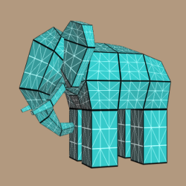
To generate a simple subdivision image like this, the tessellation evaluation shader needs to consider only the 4 corners of the patch. Since we’re using 16 control points per patch, the corners are at positions 0, 3, 12, and 15. All we have to do is lerp between those four verts, and here’s the tessellation evaluation shader for doing so:
-- TessEval

layout(quads) in;
in vec3 tcPosition[];
out vec3 tePosition;
uniform mat4 Projection;
uniform mat4 Modelview;

void main()
{
    float u = gl_TessCoord.x, v = gl_TessCoord.y;
    vec3 a = mix(tcPosition[0], tcPosition[3], u);
    vec3 b = mix(tcPosition[12], tcPosition[15], u);
    tePosition = mix(a, b, v);
    gl_Position = Projection * Modelview * vec4(tePosition, 1);
}
If you’re wondering about the strange prefixes on variables like tcPosition, flip back to the previous entry.
Bezier Smoothing
Of course, we can make Gumbo more rounded by performing proper smoothing, in which case we can obtain an image like this:
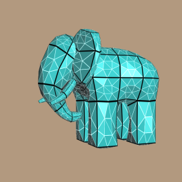
Here’s the final version of the tessellation evaluation shader:
-- TessEval

layout(quads) in;
in vec3 tcPosition[];
out vec3 tePosition;
out vec4 tePatchDistance;
uniform mat4 Projection;
uniform mat4 Modelview;
uniform mat4 B;
uniform mat4 BT;

void main()
{
    float u = gl_TessCoord.x, v = gl_TessCoord.y;

    mat4 Px = mat4(
        tcPosition[0].x, tcPosition[1].x, tcPosition[2].x, tcPosition[3].x,
        tcPosition[4].x, tcPosition[5].x, tcPosition[6].x, tcPosition[7].x,
        tcPosition[8].x, tcPosition[9].x, tcPosition[10].x, tcPosition[11].x,
        tcPosition[12].x, tcPosition[13].x, tcPosition[14].x, tcPosition[15].x );

    mat4 Py = mat4(
        tcPosition[0].y, tcPosition[1].y, tcPosition[2].y, tcPosition[3].y,
        tcPosition[4].y, tcPosition[5].y, tcPosition[6].y, tcPosition[7].y,
        tcPosition[8].y, tcPosition[9].y, tcPosition[10].y, tcPosition[11].y,
        tcPosition[12].y, tcPosition[13].y, tcPosition[14].y, tcPosition[15].y );

    mat4 Pz = mat4(
        tcPosition[0].z, tcPosition[1].z, tcPosition[2].z, tcPosition[3].z,
        tcPosition[4].z, tcPosition[5].z, tcPosition[6].z, tcPosition[7].z,
        tcPosition[8].z, tcPosition[9].z, tcPosition[10].z, tcPosition[11].z,
        tcPosition[12].z, tcPosition[13].z, tcPosition[14].z, tcPosition[15].z );

    mat4 cx = B * Px * BT;
    mat4 cy = B * Py * BT;
    mat4 cz = B * Pz * BT;

    vec4 U = vec4(u*u*u, u*u, u, 1);
    vec4 V = vec4(v*v*v, v*v, v, 1);

    float x = dot(cx * V, U);
    float y = dot(cy * V, U);
    float z = dot(cz * V, U);
    tePosition =  vec3(x, y, z);

    tePatchDistance = vec4(u, v, 1-u, 1-v);
    gl_Position = Projection * Modelview * vec4(x, y, z, 1);
}
The above shader pretty much does exactly what the Python script in my other blog entry does. Note that I also write out a vec4 of edge distances to the tePatchDistance output variable; these are used for the wireframe technique, which I’ll cover shortly.
Of course, this isn’t very efficient. Some of the calculations are being performed at every vertex, but really they only need to performed once per patch. Namely, computation of the coefficient matrices (cx, cy, and cz) should be hoisted up into the tessellation control shader. Then, tcPosition can become a representation of those matrices, rather than being coordinates for the raw control points. Alas, I ran into driver / compiler issues when I made this optimization. OpenGL 4.0 is still a young technology, and the drivers need some time to mature. I’ll dig deeper when I have time, and file bug reports against the hardware vendor that I’m using.
Black and White Lines
You may have noticed that I improved on the wireframe technique presented in my previous blog entry; I now render the triangle edges in white, and the patch edges in black. The geometry shader is exactly the same as what I presented earlier:
-- Geometry

uniform mat4 Modelview;
uniform mat3 NormalMatrix;
layout(triangles) in;
layout(triangle_strip, max_vertices = 3) out;
in vec3 tePosition[3];
in vec4 tePatchDistance[3];
out vec3 gFacetNormal;
out vec4 gPatchDistance;
out vec3 gTriDistance;

void main()
{
    vec3 A = tePosition[2] - tePosition[0];
    vec3 B = tePosition[1] - tePosition[0];
    gFacetNormal = NormalMatrix * normalize(cross(A, B));

    gPatchDistance = tePatchDistance[0];
    gTriDistance = vec3(1, 0, 0);
    gl_Position = gl_in[0].gl_Position; EmitVertex();

    gPatchDistance = tePatchDistance[1];
    gTriDistance = vec3(0, 1, 0);
    gl_Position = gl_in[1].gl_Position; EmitVertex();

    gPatchDistance = tePatchDistance[2];
    gTriDistance = vec3(0, 0, 1);
    gl_Position = gl_in[2].gl_Position; EmitVertex();

    EndPrimitive();
}
The fragment shader is almost the same, except that I’m taking the min of four distances for the patch edges. I’m also drawing triangle edges in white, and I snuck in a specular component to the lighting computation:
-- Fragment

out vec4 FragColor;
in vec3 gFacetNormal;
in vec3 gTriDistance;
in vec4 gPatchDistance;
uniform vec3 LightPosition;
uniform vec3 DiffuseMaterial;
uniform vec3 AmbientMaterial;
uniform vec3 SpecularMaterial;
uniform float Shininess;
const vec3 InnerLineColor = vec3(1, 1, 1);
const bool DrawLines = false;

float amplify(float d, float scale, float offset)
{
    d = scale * d + offset;
    d = clamp(d, 0, 1);
    d = 1 - exp2(-2*d*d);
    return d;
}

void main()
{
    vec3 N = normalize(gFacetNormal);
    vec3 L = LightPosition;
    vec3 E = vec3(0, 0, 1);
    vec3 H = normalize(L + E);

    float df = abs(dot(N, L));
    float sf = abs(dot(N, H));
    sf = pow(sf, Shininess);
    vec3 color = AmbientMaterial + df * DiffuseMaterial + sf * SpecularMaterial;

    if (DrawLines) {
        float d1 = min(min(gTriDistance.x, gTriDistance.y), gTriDistance.z);
        float d2 = min(min(min(gPatchDistance.x, gPatchDistance.y), gPatchDistance.z), gPatchDistance.w);
        d1 = 1 - amplify(d1, 50, -0.5);
        d2 = amplify(d2, 50, -0.5);
        color = d2 * color + d1 * d2 * InnerLineColor;
    }

    FragColor = vec4(color, 1.0);
}
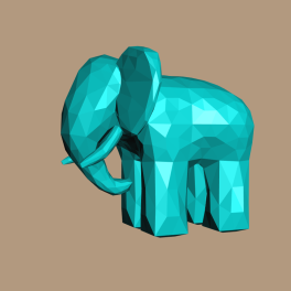
That’s about it! Here’s Gumbo with per-facet normals, but with DrawLines turned off:
Downloads
The demo code uses a subset of the Pez ecosystem, which is included in the zip below. (The Pez ecosystem is a handful of tiny libraries whose source is included directly in the project.)
I consider this code to be on the public domain. To run it, you’ll need CMake, a very up-to-date graphics driver, and a very modern graphics card.
Triangle Tessellation with OpenGL 4.0
This is the first of a two-part article on tessellation shaders with OpenGL 4.0+. This entry gives an overview of tessellation and walks through an example of simple triangle subdivision; in the next entry, we’ll focus on quad subdivision.
Reviewing Geometry Shaders
When Geometry Shaders (GS) first came out, we were all excited because we could finally write a shader that could “see” all the verts in a triangle at once. And finally, the GPU could produce more primitives than it consumed.
The GS unit turned out to be convenient for certain effects, but overall it was somewhat disappointing. It was not designed for large-scale amplification of vertex data. The GS processing for a single primitive was initially limited to a single processing unit. Most GS programs had a serial loop that simply pushed out the verts of the new primitive(s), one vertex after another. They didn’t do a great job of leveraging the massive parallelism in GPUs. Nowadays you can do a bit better by specifying an invocations count at the top of your GS, like so:
layout(triangles, invocations = 3) in;
This tells the GPU that your GS should run three times on a single primitive. You can figure out which vert you’re on by looking at the built-in gl_InvocationID variable.
The New OpenGL 4.0+ Pipeline
Although adding multiple GS invocations was helpful, performing highly-efficient subdivision demanded brand new stages in the pipeline. Now is the time for the obligatory diagram: (I used a red pen for the stages that are new to OpenGL 4.0)
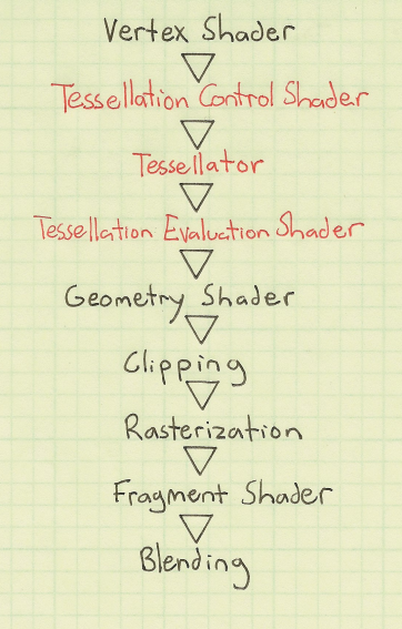
So, we now have two additional programmable stages at our disposal: Tessellation Control and Tessellation Evaluation. They both execute on a per-vertex basis, so their programs typically don’t have serial loops like the old-fashioned geometry programs did. However, much like geometry shaders, they can “see” all the verts in a single primitive.
To work with tessellation shaders, OpenGL now has a new primitive type: GL_PATCHES. Unlike GL_TRIANGLES (where every 3 verts spawns a triangle) or GL_TRIANGLE_STRIP (where every 1 vert spawns a new triangle), the number of verts in a patch is configurable:
glPatchParameteri(GL_PATCH_VERTICES, 16);       // tell OpenGL that every patch has 16 verts
glDrawArrays(GL_PATCHES, firstVert, vertCount); // draw a bunch of patches
The Tessellation Control (TC) shader is kinda like a Vertex Shader (VS) with super-vision. Much like a VS program, each TC program transforms only one vertex, and the number of execution instances is the same as the number of verts in your OpenGL draw call. The Tessellation Evaluation (TE) shader, however, usually processes more verts than you sent down in your draw call. That’s because the “Tessellator” (the stage between the two new shaders) generates brand new verts by interpolating between the existing verts.
As the name implies, the TC shader has some control over how the Tessellator generates new verts. This is done through the gl_TessLevelInner and gl_TessLevelOuter output variables. More on these later.
Another way of controlling how the Tessellator generates verts is through the layout qualifier on the TE shader’s inputs. You’ll often see a TE shader with something like this at the top:
layout(triangles, equal_spacing, cw) in;
This specifies three things: a primitive mode, a vertex spacing, and an ordering. The latter two are optional and they have reasonable defaults — I won’t go into detail about them here. As for the primitive mode, there are three choices: triangles, quads, and isolines. As mentioned earlier, in this article I’ll focus on triangles; for more on quads, see my next article.
Inner and Outer Tess Levels
Simply put, the inner tessellation level controls the number of “nested” primitives, and the outer tessellation level controls the number of times to subdivide each edge. The gl_TessLevelInner and gl_TessLevelOuter variable are both arrays-of-float, but with triangle subdivision, there’s only one element in the inner array. The outer array has three elements, one for each side of the triangle. In both arrays, a value of 1 indicates no subdivision whatsoever. For the inner tess level, a value of 2 means that there’s only one nested triangle, but it’s degenerate; it’s just a single point. It’s not till tess level 3 that you see a miniatured of the original triangle inside the original triangle.
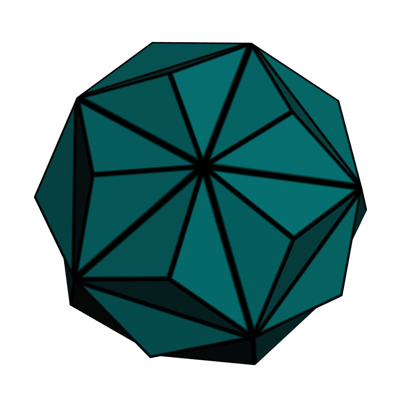
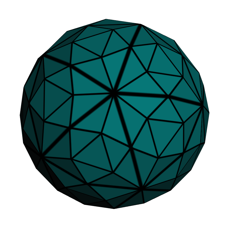
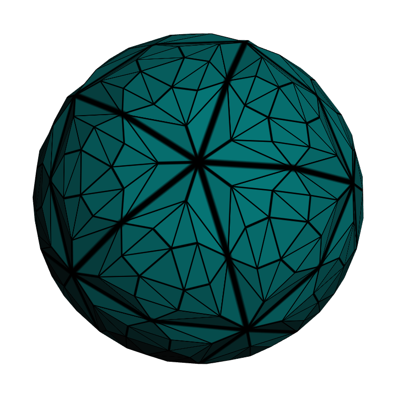
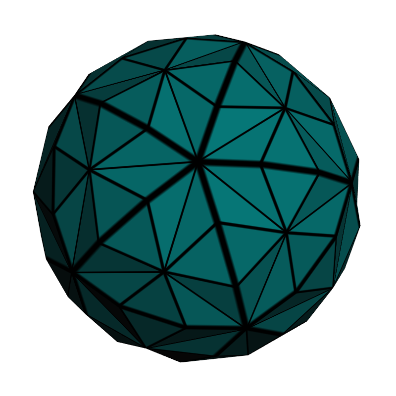
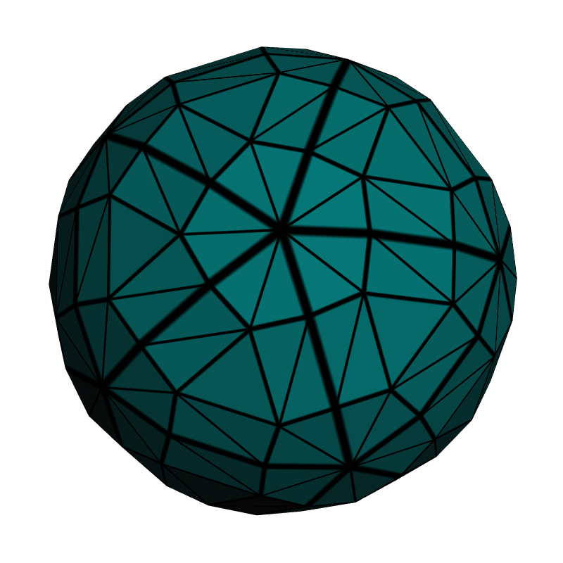
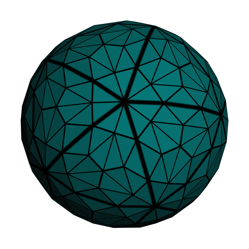
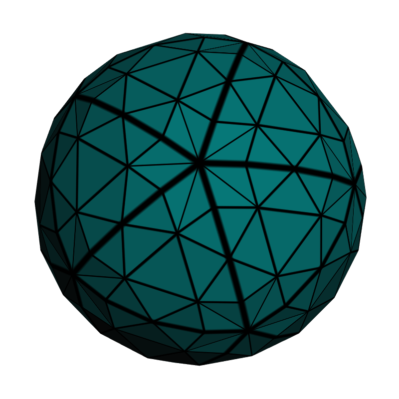
Since the tess levels are controlled at the shader level (as opposed to the OpenGL API level), you can do awesome things with dynamic level-of-detail. However, for demonstration purposes, we’ll limit ourselves to the simple case here. We’ll set the inner tess level to a hardcoded value, regardless of distance-from-camera. For the outer tess level, we’ll set all three edges to the same value. Here’s a little diagram that shows how triangle-to-triangle subdivision can be configured with our demo program, which sends an icosahedron to OpenGL:
| Inner = 1 | Inner = 2 | Inner = 3 | Inner = 4 | |
| Outer = 1 | 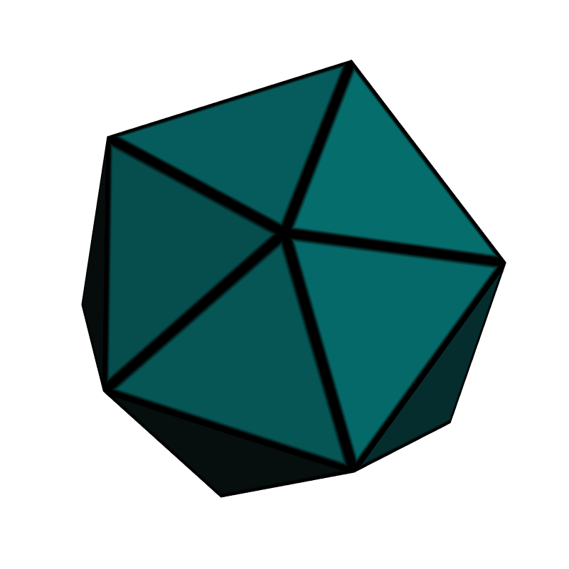 |
 |
 |
 |
| Outer = 2 | 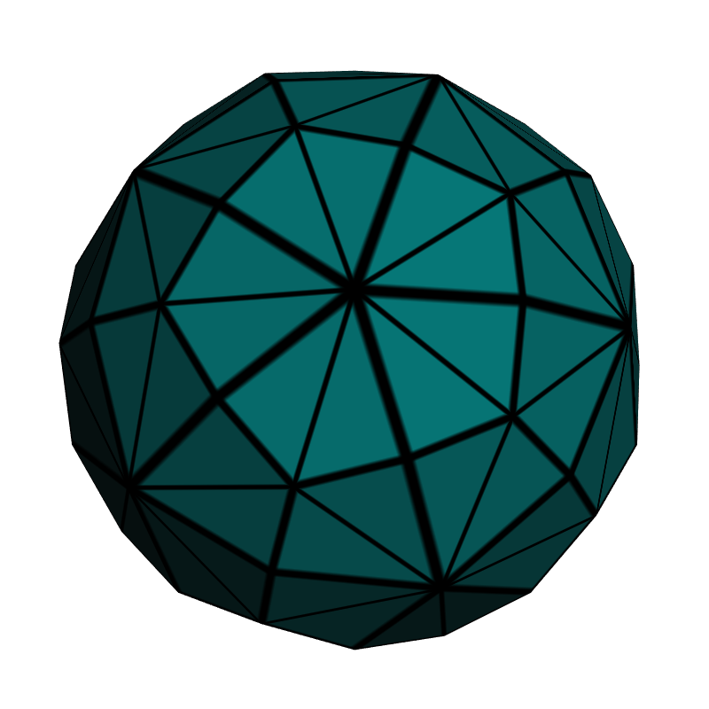 |
 |
 |
 |
| Outer = 3 |  |
 |
 |
 |
| Outer = 4 | 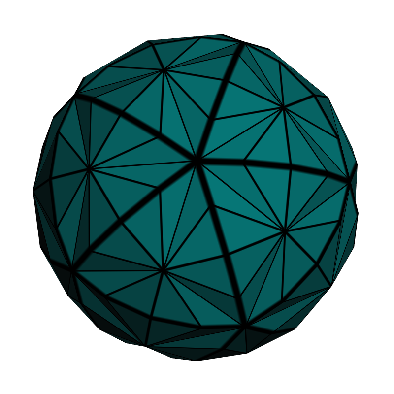 |
 |
 |
 |
Show Me The Code
Building the VAO for the icosahedron isn’t the subject of this article, but for completeness here’s the C code for doing so:
static void CreateIcosahedron()
{
    const int Faces[] = {
        2, 1, 0,
        3, 2, 0,
        4, 3, 0,
        5, 4, 0,
        1, 5, 0,
        11, 6,  7,
        11, 7,  8,
        11, 8,  9,
        11, 9,  10,
        11, 10, 6,
        1, 2, 6,
        2, 3, 7,
        3, 4, 8,
        4, 5, 9,
        5, 1, 10,
        2,  7, 6,
        3,  8, 7,
        4,  9, 8,
        5, 10, 9,
        1, 6, 10 };

    const float Verts[] = {
         0.000f,  0.000f,  1.000f,
         0.894f,  0.000f,  0.447f,
         0.276f,  0.851f,  0.447f,
        -0.724f,  0.526f,  0.447f,
        -0.724f, -0.526f,  0.447f,
         0.276f, -0.851f,  0.447f,
         0.724f,  0.526f, -0.447f,
        -0.276f,  0.851f, -0.447f,
        -0.894f,  0.000f, -0.447f,
        -0.276f, -0.851f, -0.447f,
         0.724f, -0.526f, -0.447f,
         0.000f,  0.000f, -1.000f };

    IndexCount = sizeof(Faces) / sizeof(Faces[0]);

    // Create the VAO:
    GLuint vao;
    glGenVertexArrays(1, &vao);
    glBindVertexArray(vao);

    // Create the VBO for positions:
    GLuint positions;
    GLsizei stride = 3 * sizeof(float);
    glGenBuffers(1, &positions);
    glBindBuffer(GL_ARRAY_BUFFER, positions);
    glBufferData(GL_ARRAY_BUFFER, sizeof(Verts), Verts, GL_STATIC_DRAW);
    glEnableVertexAttribArray(PositionSlot);
    glVertexAttribPointer(PositionSlot, 3, GL_FLOAT, GL_FALSE, stride, 0);

    // Create the VBO for indices:
    GLuint indices;
    glGenBuffers(1, &indices);
    glBindBuffer(GL_ELEMENT_ARRAY_BUFFER, indices);
    glBufferData(GL_ELEMENT_ARRAY_BUFFER, sizeof(Faces), Faces, GL_STATIC_DRAW);
}
Our vertex shader is even more boring:
-- Vertex

in vec4 Position;
out vec3 vPosition;

void main()
{
    vPosition = Position.xyz;
}
We use a special naming convention for in/out variables. If we need to trickle Foo through the entire pipeline, here’s how we avoid naming collisions:
- Foo is the original vertex attribute (sent from the CPU)
- vFoo is the output of the VS and the input to the TC shader
- tcFoo is the output of the TC shader and the input to the TE shader
- teFoo is the output of the TE shader and the input to the GS
- gFoo is the output of the GS and the input to the FS
Now, without further ado, we’re ready to show off our tessellation control shader:
-- TessControl

layout(vertices = 3) out;
in vec3 vPosition[];
out vec3 tcPosition[];
uniform float TessLevelInner;
uniform float TessLevelOuter;

#define ID gl_InvocationID

void main()
{
    tcPosition[ID] = vPosition[ID];
    if (ID == 0) {
        gl_TessLevelInner[0] = TessLevelInner;
        gl_TessLevelOuter[0] = TessLevelOuter;
        gl_TessLevelOuter[1] = TessLevelOuter;
        gl_TessLevelOuter[2] = TessLevelOuter;
    }
}
That’s almost as boring as our vertex shader! Note that per-patch outputs (such as gl_TessLevelInner) only need to be written once. We enclose them in an if so that we only bother writing to them from a single execution thread. Incidentally, you can create custom per-patch variables if you’d like; simply use the patch out qualifier when declaring them.
Here’s the tessellation control shader that we use for our icosahedron demo:
-- TessEval

layout(triangles, equal_spacing, cw) in;
in vec3 tcPosition[];
out vec3 tePosition;
out vec3 tePatchDistance;
uniform mat4 Projection;
uniform mat4 Modelview;

void main()
{
    vec3 p0 = gl_TessCoord.x * tcPosition[0];
    vec3 p1 = gl_TessCoord.y * tcPosition[1];
    vec3 p2 = gl_TessCoord.z * tcPosition[2];
    tePatchDistance = gl_TessCoord;
    tePosition = normalize(p0 + p1 + p2);
    gl_Position = Projection * Modelview * vec4(tePosition, 1);
}
The built-in gl_TessCoord variable lets us know where we are within the patch. In this case, the primitive mode is triangles, so gl_TessCoord is a barycentric coordinate. If we were performing quad subdivision, then it would be a UV coordinate and we’d ignore the Z component.
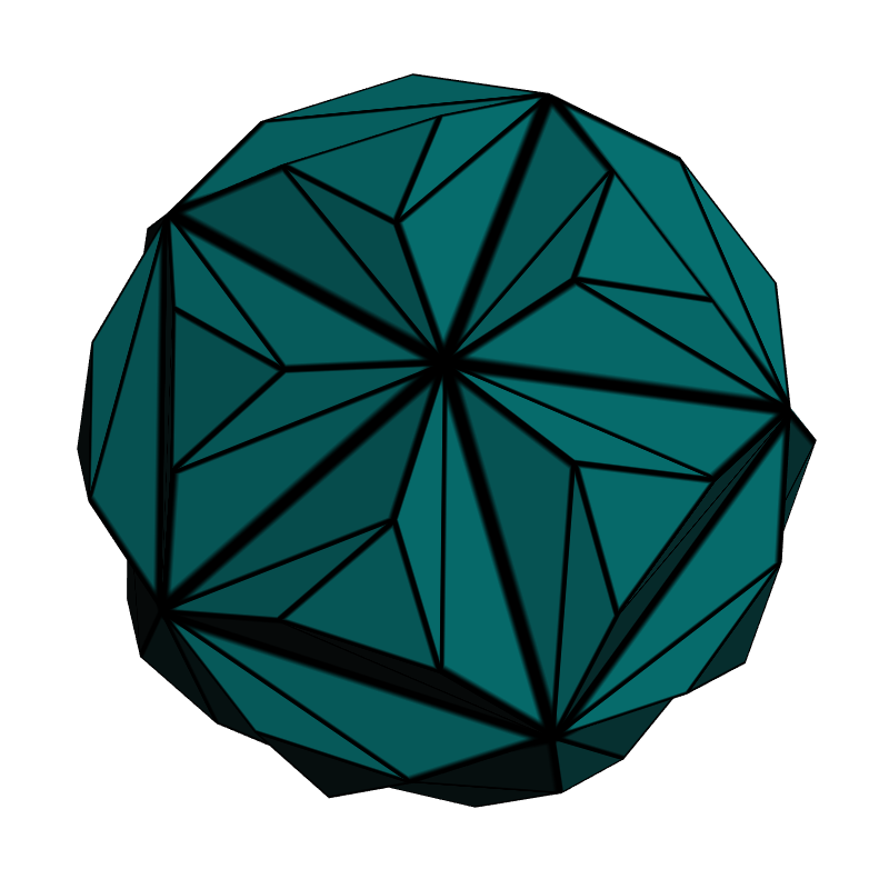
Our demo subdivides the icosahedron in such a way that it approaches a perfect unit sphere, so we use normalize to push the new verts onto the sphere’s surface.
The tePatchDistance output variable will be used by the fragment shader to visualize the edges of the patch; this brings us to the next section.
Geometry Shaders Are Still Fun!
Geometry shaders are now considered the runt of the litter, but sometimes they’re useful for certain techniques, like computing facet normals on the fly, or creating a nice single-pass wireframe. In this demo, we’ll do both. We’re intentionally using non-smooth normals (in other words, the lighting is the same across the triangle) because it helps visualize the tessellation.
For a brief overview on rendering nice wireframes with geometry shaders, check out this SIGGRAPH sketch. To summarize, the GS needs to send out a vec3 “edge distance” at each corner; these automatically get interpolated by the rasterizer, which gives the fragment shader a way to determine how far the current pixel is from the nearest edge.
We’ll extend the wireframe technique here because we wish the pixel shader to highlight two types of edges differently. The edge of the final triangle is drawn with a thin line, and the edge of the original patch is drawn with a thick line.
-- Geometry

uniform mat4 Modelview;
uniform mat3 NormalMatrix;
layout(triangles) in;
layout(triangle_strip, max_vertices = 3) out;
in vec3 tePosition[3];
in vec3 tePatchDistance[3];
out vec3 gFacetNormal;
out vec3 gPatchDistance;
out vec3 gTriDistance;

void main()
{
    vec3 A = tePosition[2] - tePosition[0];
    vec3 B = tePosition[1] - tePosition[0];
    gFacetNormal = NormalMatrix * normalize(cross(A, B));

    gPatchDistance = tePatchDistance[0];
    gTriDistance = vec3(1, 0, 0);
    gl_Position = gl_in[0].gl_Position; EmitVertex();

    gPatchDistance = tePatchDistance[1];
    gTriDistance = vec3(0, 1, 0);
    gl_Position = gl_in[1].gl_Position; EmitVertex();

    gPatchDistance = tePatchDistance[2];
    gTriDistance = vec3(0, 0, 1);
    gl_Position = gl_in[2].gl_Position; EmitVertex();

    EndPrimitive();
}
As you can see, we used the classic one-at-a-time method in our GS, rather than specifying an invocations count other than 1. This is fine for demo purposes.
Our fragment shader does some per-pixel lighting (which is admittedly silly; the normal is the same across the triangle, so we should’ve performed lighting much earlier) and takes the minimum of all incoming distances to see if the current pixel lies near an edge.
out vec4 FragColor;
in vec3 gFacetNormal;
in vec3 gTriDistance;
in vec3 gPatchDistance;
in float gPrimitive;
uniform vec3 LightPosition;
uniform vec3 DiffuseMaterial;
uniform vec3 AmbientMaterial;

float amplify(float d, float scale, float offset)
{
    d = scale * d + offset;
    d = clamp(d, 0, 1);
    d = 1 - exp2(-2*d*d);
    return d;
}

void main()
{
    vec3 N = normalize(gFacetNormal);
    vec3 L = LightPosition;
    float df = abs(dot(N, L));
    vec3 color = AmbientMaterial + df * DiffuseMaterial;

    float d1 = min(min(gTriDistance.x, gTriDistance.y), gTriDistance.z);
    float d2 = min(min(gPatchDistance.x, gPatchDistance.y), gPatchDistance.z);
    color = amplify(d1, 40, -0.5) * amplify(d2, 60, -0.5) * color;

    FragColor = vec4(color, 1.0);
}
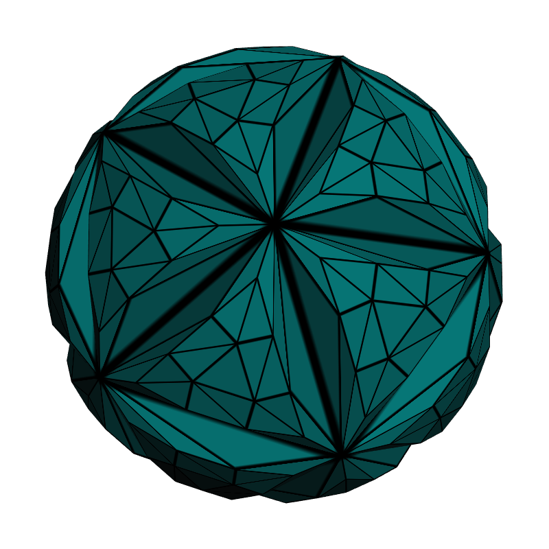
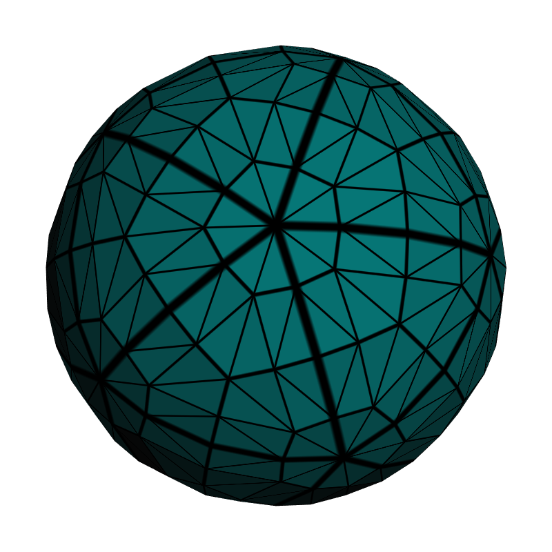
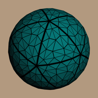
That completes the shader code for the demo, and we managed to specify code for all of the five shader stages in the modern GPU pipeline. Here’s the final output using a tessellation level of 4 for both inner and outer:
Downloads
The demo code uses a subset of the Pez ecosystem, which is included in the zip below. (The Pez ecosystem is a handful of tiny libraries whose source is included directly in the project).
I consider this code to be on the public domain. To run it, you’ll need CMake, a very up-to-date graphics driver, and a very modern graphics card. Good luck!