Quad Tessellation with OpenGL 4.0
This is the second of a two-part article on tessellation shaders with OpenGL 4.0+. This entry walks through simple bezier patch subdivision; the previous entry gave an overview of tessellation and triangle subdivision. This article is going to be short and sweet.
You might also want to review my article on patch evaluation in Python, and Ken Perlin’s course notes on patches.
Quad Subdivision
Whenever implementing a tessellation scheme, I find it best to initially get things going without any smoothing. In other words, simply divide up the patch without introducing any curvature. Here’s how our demo renders Catmull’s Gumbo model using the subdivided-but-not-smoothed approach:
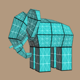
To generate a simple subdivision image like this, the tessellation evaluation shader needs to consider only the 4 corners of the patch. Since we’re using 16 control points per patch, the corners are at positions 0, 3, 12, and 15. All we have to do is lerp between those four verts, and here’s the tessellation evaluation shader for doing so:
-- TessEval

layout(quads) in;
in vec3 tcPosition[];
out vec3 tePosition;
uniform mat4 Projection;
uniform mat4 Modelview;

void main()
{
    float u = gl_TessCoord.x, v = gl_TessCoord.y;
    vec3 a = mix(tcPosition[0], tcPosition[3], u);
    vec3 b = mix(tcPosition[12], tcPosition[15], u);
    tePosition = mix(a, b, v);
    gl_Position = Projection * Modelview * vec4(tePosition, 1);
}
If you’re wondering about the strange prefixes on variables like tcPosition, flip back to the previous entry.
Bezier Smoothing
Of course, we can make Gumbo more rounded by performing proper smoothing, in which case we can obtain an image like this:
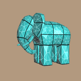
Here’s the final version of the tessellation evaluation shader:
-- TessEval

layout(quads) in;
in vec3 tcPosition[];
out vec3 tePosition;
out vec4 tePatchDistance;
uniform mat4 Projection;
uniform mat4 Modelview;
uniform mat4 B;
uniform mat4 BT;

void main()
{
    float u = gl_TessCoord.x, v = gl_TessCoord.y;

    mat4 Px = mat4(
        tcPosition[0].x, tcPosition[1].x, tcPosition[2].x, tcPosition[3].x,
        tcPosition[4].x, tcPosition[5].x, tcPosition[6].x, tcPosition[7].x,
        tcPosition[8].x, tcPosition[9].x, tcPosition[10].x, tcPosition[11].x,
        tcPosition[12].x, tcPosition[13].x, tcPosition[14].x, tcPosition[15].x );

    mat4 Py = mat4(
        tcPosition[0].y, tcPosition[1].y, tcPosition[2].y, tcPosition[3].y,
        tcPosition[4].y, tcPosition[5].y, tcPosition[6].y, tcPosition[7].y,
        tcPosition[8].y, tcPosition[9].y, tcPosition[10].y, tcPosition[11].y,
        tcPosition[12].y, tcPosition[13].y, tcPosition[14].y, tcPosition[15].y );

    mat4 Pz = mat4(
        tcPosition[0].z, tcPosition[1].z, tcPosition[2].z, tcPosition[3].z,
        tcPosition[4].z, tcPosition[5].z, tcPosition[6].z, tcPosition[7].z,
        tcPosition[8].z, tcPosition[9].z, tcPosition[10].z, tcPosition[11].z,
        tcPosition[12].z, tcPosition[13].z, tcPosition[14].z, tcPosition[15].z );

    mat4 cx = B * Px * BT;
    mat4 cy = B * Py * BT;
    mat4 cz = B * Pz * BT;

    vec4 U = vec4(u*u*u, u*u, u, 1);
    vec4 V = vec4(v*v*v, v*v, v, 1);

    float x = dot(cx * V, U);
    float y = dot(cy * V, U);
    float z = dot(cz * V, U);
    tePosition =  vec3(x, y, z);

    tePatchDistance = vec4(u, v, 1-u, 1-v);
    gl_Position = Projection * Modelview * vec4(x, y, z, 1);
}
The above shader pretty much does exactly what the Python script in my other blog entry does. Note that I also write out a vec4 of edge distances to the tePatchDistance output variable; these are used for the wireframe technique, which I’ll cover shortly.
Of course, this isn’t very efficient. Some of the calculations are being performed at every vertex, but really they only need to performed once per patch. Namely, computation of the coefficient matrices (cx, cy, and cz) should be hoisted up into the tessellation control shader. Then, tcPosition can become a representation of those matrices, rather than being coordinates for the raw control points. Alas, I ran into driver / compiler issues when I made this optimization. OpenGL 4.0 is still a young technology, and the drivers need some time to mature. I’ll dig deeper when I have time, and file bug reports against the hardware vendor that I’m using.
Black and White Lines
You may have noticed that I improved on the wireframe technique presented in my previous blog entry; I now render the triangle edges in white, and the patch edges in black. The geometry shader is exactly the same as what I presented earlier:
-- Geometry

uniform mat4 Modelview;
uniform mat3 NormalMatrix;
layout(triangles) in;
layout(triangle_strip, max_vertices = 3) out;
in vec3 tePosition[3];
in vec4 tePatchDistance[3];
out vec3 gFacetNormal;
out vec4 gPatchDistance;
out vec3 gTriDistance;

void main()
{
    vec3 A = tePosition[2] - tePosition[0];
    vec3 B = tePosition[1] - tePosition[0];
    gFacetNormal = NormalMatrix * normalize(cross(A, B));

    gPatchDistance = tePatchDistance[0];
    gTriDistance = vec3(1, 0, 0);
    gl_Position = gl_in[0].gl_Position; EmitVertex();

    gPatchDistance = tePatchDistance[1];
    gTriDistance = vec3(0, 1, 0);
    gl_Position = gl_in[1].gl_Position; EmitVertex();

    gPatchDistance = tePatchDistance[2];
    gTriDistance = vec3(0, 0, 1);
    gl_Position = gl_in[2].gl_Position; EmitVertex();

    EndPrimitive();
}
The fragment shader is almost the same, except that I’m taking the min of four distances for the patch edges. I’m also drawing triangle edges in white, and I snuck in a specular component to the lighting computation:
-- Fragment

out vec4 FragColor;
in vec3 gFacetNormal;
in vec3 gTriDistance;
in vec4 gPatchDistance;
uniform vec3 LightPosition;
uniform vec3 DiffuseMaterial;
uniform vec3 AmbientMaterial;
uniform vec3 SpecularMaterial;
uniform float Shininess;
const vec3 InnerLineColor = vec3(1, 1, 1);
const bool DrawLines = false;

float amplify(float d, float scale, float offset)
{
    d = scale * d + offset;
    d = clamp(d, 0, 1);
    d = 1 - exp2(-2*d*d);
    return d;
}

void main()
{
    vec3 N = normalize(gFacetNormal);
    vec3 L = LightPosition;
    vec3 E = vec3(0, 0, 1);
    vec3 H = normalize(L + E);

    float df = abs(dot(N, L));
    float sf = abs(dot(N, H));
    sf = pow(sf, Shininess);
    vec3 color = AmbientMaterial + df * DiffuseMaterial + sf * SpecularMaterial;

    if (DrawLines) {
        float d1 = min(min(gTriDistance.x, gTriDistance.y), gTriDistance.z);
        float d2 = min(min(min(gPatchDistance.x, gPatchDistance.y), gPatchDistance.z), gPatchDistance.w);
        d1 = 1 - amplify(d1, 50, -0.5);
        d2 = amplify(d2, 50, -0.5);
        color = d2 * color + d1 * d2 * InnerLineColor;
    }

    FragColor = vec4(color, 1.0);
}
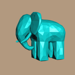
That’s about it! Here’s Gumbo with per-facet normals, but with DrawLines turned off:
Downloads
The demo code uses a subset of the Pez ecosystem, which is included in the zip below. (The Pez ecosystem is a handful of tiny libraries whose source is included directly in the project.)
I consider this code to be on the public domain. To run it, you’ll need CMake, a very up-to-date graphics driver, and a very modern graphics card.