Archive for the ‘opengl silhouette’ tag
Silhouette Extraction
Some of my previous entries used the geometry shader (GS) to highlight certain triangle edges by passing new information to the fragment shader. The GS can also be used generate long, thin quads along those edges; this lets you apply texturing for sketchy effects. In the case of silhouette lines, you can create an anti-aliased border along the boundary of the model, without the cost of true multisampling.
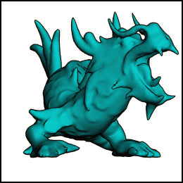
In this article, I’ll show how to generate silhouettes using GLSL geometry shaders. At the end of the article, I provide the complete demo code for drawing the dragon depicted here. I tested the demo with Ubuntu (gcc), and Windows (Visual Studio 2010).
Old School Silhouettes
Just for fun, I want to point out a classic two-pass method for generating silhouettes, used in the days before shaders. I wouldn’t recommend it nowadays; it does not highlight creases and “core” OpenGL no longer supports smooth/wide lines anyway. This technique can be found in Under the Shade of the Rendering Tree by John Lander:
- Draw front faces:
- glPolygonMode(GL_FRONT, GL_FILL)
- glDepthFunc(GL_LESS)
- Draw back faces:
- glPolygonMode(GL_BACK, GL_LINE)
- glDepthFunc(GL_LEQUAL)
Ah, brings back memories…
Computing Adjacency
To detect silhouettes and creases, the GS examines the facet normals of adjacent triangles. So, we’ll need to send down the verts using GL_TRIANGLES_ADJACENCY:
glDrawElements(GL_TRIANGLES_ADJACENCY, // primitive type
               triangleCount*6,        // index count
               GL_UNSIGNED_SHORT,      // index type
               0);                     // start index
Six verts per triangle seems like an egregious redundancy of data, but keep in mind that it enlarges your index VBO, not your attributes VBO.
Typical mesh files don’t include adjacency information, but it’s easy enough to compute in your application. A wonderfully simple data structure for algorithms like this is the Half-Edge Table.
For low-level mesh algorithms, I enjoy using C99 rather than C++. I find that avoiding STL makes life a bit easier when debugging, and it encourages me to use memory efficiently. Here’s a half-edge structure in C:
typedef struct HalfEdgeRec
{
    unsigned short Vert;      // Vertex index at the end of this half-edge
    struct HalfEdgeRec* Twin; // Oppositely oriented adjacent half-edge
    struct HalfEdgeRec* Next; // Next half-edge around the face
} HalfEdge;
If you’ve got a half-edge structure for your mesh, it’s a simple linear-time algorithm to expand an index buffer to include adjacency information. Check out the downloads section to see how I did it.
By the way, you do need an associative array to build a half-edge table when loading model data from a traditional mesh file. In C++, this is all too easy because of helpful libraries like std::hash_map and Google’s Sparse Hash. For C99, I find that Judy arrays provide a compelling way of creating associative arrays.
Basic Fins
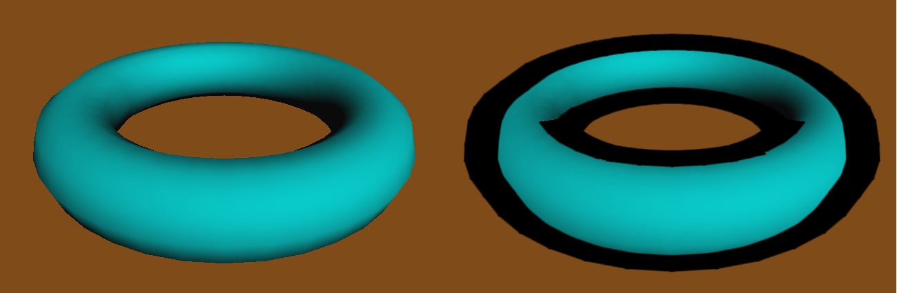
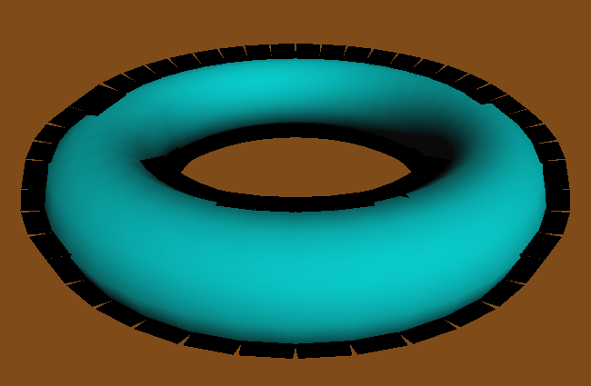
Now that we’ve got preliminaries out of the way, let’s start on the silhouette extrusion algorithm. We’ll start simple and make enhancements in the coming sections. We’ll use this torus as the demo model. The image on the left shows the starting point; the image on the right is our goal.
Silhouette lines occur on the boundary between front-facing triangles and back-facing triangles. Let’s define a function that takes three triangle corners (in screen space), returning true for front-facing triangles. To pull this off, we can take the cross product of two sides. If the Z component of the result is positive, then it’s front-facing. Since we can ignore the X and Y components of the result, this reduces to:
bool IsFront(vec2 A, vec2 B, vec2 C)
{
    return 0 < (A.x * B.y - B.x * A.y) + (B.x * C.y - C.x * B.y) + (C.x * A.y - A.x * C.y);
}
Incidentally, the length of the cross-product is equal to twice the area of the triangle. But I digress…
The next function emits a long, thin quadrilateral between two points. To do this, we’ll add an extrusion vector to the two endpoints. In the following snippet, N is the extrusion vector, computed by taking the perpendicular of the normalized vector between the two points, then scaling it by half the desired line width:
uniform float HalfWidth;

void EmitEdge(vec2 P0, vec2 P1)
{
    vec2 V = normalize(P1 - P0);
    vec2 N = vec2(-V.y, V.x) * HalfWidth;

    gl_Position = vec4(P0 - N, 0, 1); EmitVertex();
    gl_Position = vec4(P0 + N, 0, 1); EmitVertex();
    gl_Position = vec4(P1 - N, 0, 1); EmitVertex();
    gl_Position = vec4(P1 + N, 0, 1); EmitVertex();
    EndPrimitive();
}
Next let’s write main() for the geometry shader. It checks if the current triangle is frontfacing, then emits a quad for each backfacing neighbor:
layout(triangles_adjacency) in;
layout(triangle_strip, max_vertices = 12) out;

void main()
{
    vec2 v0 = gl_in[0].gl_Position.xy;
    vec2 v1 = gl_in[1].gl_Position.xy;
    vec2 v2 = gl_in[2].gl_Position.xy;
    vec2 v3 = gl_in[3].gl_Position.xy;
    vec2 v4 = gl_in[4].gl_Position.xy;
    vec2 v5 = gl_in[5].gl_Position.xy;

    if (IsFront(v0, v2, v4)) {
        if (!IsFront(v0, v1, v2)) EmitEdge(v0, v2);
        if (!IsFront(v2, v3, v4)) EmitEdge(v2, v4);
        if (!IsFront(v0, v4, v5)) EmitEdge(v4, v0);
    }
}
Here’s the result:
Not too pretty. There are three problems with this silhouette:
- The outer edge of the fin needs some antialiasing.
- We’re only seeing the upper half of the fin.
- There’s a gap between neighboring fins.
We’ll address each of these issues in the coming sections.
Antialiased Fins
First let’s add some antialiasing to those fins. To pull this off, we’ll attach a distance-from-center value to each corner of the quad. In the fragment shader, we can use these values to see how far the current pixel is from the edge. If it’s less than a couple pixels away, it fades the alpha value. The EmitEdge function now becomes:
out float gDist;
uniform float HalfWidth;

void EmitEdge(vec2 P0, vec2 P1)
{
    vec2 V = normalize(P1 - P0);
    vec2 N = vec2(-V.y, V.x) * HalfWidth;

    gDist = +HalfWidth;
    gl_Position = vec4(P0 - N, 0, 1); EmitVertex();
    gDist = -HalfWidth;
    gl_Position = vec4(P0 + N, 0, 1); EmitVertex();
    gDist = +HalfWidth;
    gl_Position = vec4(P1 - N, 0, 1); EmitVertex();
    gDist = -HalfWidth;
    gl_Position = vec4(P1 + N, 0, 1); EmitVertex();
    EndPrimitive();
}
Next is the fragment shader, which uses the tipLength variable to represent the length of the desired alpha gradient. We leverage GLSL’s built-in fwidth function to prevent it from looking fuzzy when zoomed in:
in float gDist;
out vec4 fColor;
uniform float HalfWidth;
const vec3 LineColor = vec3(0, 0, 0);

void main()
{
    float alpha = 1.0;
    float d = abs(gDist);
    float tipLength = 2.0 * fwidth(d);
    if (d > HalfWidth - tipLength)
        alpha = 1.0 - (d - HalfWidth + tipLength) / tipLength;

    fColor = vec4(LineColor, alpha);
}
Here’s the result:

The Spine Test
We extruded in both directions, so why are we seeing only half of the fin? The issue lies with depth testing. We could simply disable all depth testing during the silhouette pass, but then we’d see creases from the opposite side of the model. The correct trick is to perform depth testing along the centerline of the quad, rather than at the current fragment. This method is called spine testing, and it was introduced by a recent paper from Forrester Cole and Adam Finkelstein.
In order to perform custom depth testing, we’ll need to do an early Z pass. An early Z pass is often useful for other reasons, especially for scenes with high depth complexity. In our demo program, we generate a G-Buffer containing normals and depths:
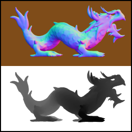
The normals are used for per-pixel lighting while the depths are used for spine testing. The fragment shader for G-Buffer generation is exceedingly simple; it simply transforms the normals into the [0,1] range and writes them out:
in vec3 vNormal;
out vec3 fColor;

void main()
{
    fColor = (vNormal + 1.0) * 0.5;
}
When rendering silhouette lines, the fragment shader will need texture coordinates for the spine. The geometry shader comes to the rescue again. It simply transforms the device coordinates of the quad’s endpoints into texture coordinates, then writes them out to a new output variable:
out float gDist;
out vec2 gSpine;
uniform float HalfWidth;

void EmitEdge(vec2 P0, vec2 P1)
{
    vec2 V = normalize(P1 - P0);
    vec2 N = vec2(-V.y, V.x) * HalfWidth;

    gSpine = (P0 + 1.0) * 0.5;
    gDist = +HalfWidth;
    gl_Position = vec4(P0 - N, 0, 1); EmitVertex();
    gDist = -HalfWidth;
    gl_Position = vec4(P0 + N, 0, 1); EmitVertex();
    gSpine = (P1 + 1.0) * 0.5;
    gDist = +HalfWidth;
    gl_Position = vec4(P1 - N, 0, 1); EmitVertex();
    gDist = -HalfWidth;
    gl_Position = vec4(P1 + N, 0, 1); EmitVertex();
    EndPrimitive();
}
Next we enhance the fragment shader to issue a discard for fragments that fail the custom depth test:
in float gDist;
in vec2 gSpine;
out vec4 fColor;
uniform float HalfWidth;
uniform sampler2D DepthSampler;
uniform vec2 Size;

void main()
{
    vec2 texCoord = gSpine;
    float depth = texture2D(DepthSampler, texCoord).r;
    if (depth < gl_FragCoord.z)
        discard;

    float alpha = 1.0;
    float d = abs(gDist);
    float tipLength = 2.0 * fwidth(d);
    if (d > HalfWidth - tipLength)
        alpha = 1.0 - (d - HalfWidth + tipLength) / tipLength;

    fColor = vec4(0, 0, 0, alpha);
}
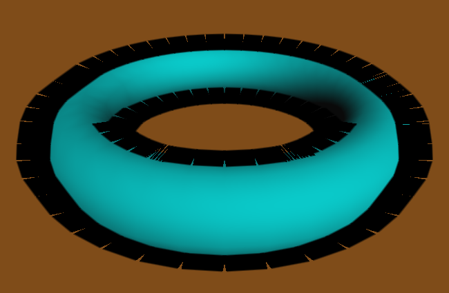
Here’s the result. Note that the fin now extends below the contour, allowing you to see the AA on both ends.
Mind the Gap!
Next let’s fill in those gaps, creating the illusion of a single, seamless line. Some researchers create new triangles on either end of the fin, using vertex normals to determine the shape of those triangles. In practice I found this tricky to work with, especially since vertex normals are usually intended for 3D lighting, not screen-space effects. I found it easier to simply extend the lengths of the quads that I’m already generating. Sure, this causes too much overlap in some places, but it doesn’t seem to hurt the final image quality much. The percentage by which to extend the fin length is controlled via the OverhangLength shader uniform in the following snippet:
out float gDist;
out vec2 gSpine;
uniform float HalfWidth;
uniform float OverhangLength;

void EmitEdge(vec2 P0, vec2 P1)
{
    vec2 E = OverhangLength * (P1 - P0);
    vec2 V = normalize(E);
    vec2 N = vec2(-V.y, V.x) * HalfWidth;

    gSpine = (P0 + 1.0) * 0.5;
    gDist = +HalfWidth;
    gl_Position = vec4(P0 - N - E, 0, 1); EmitVertex();
    gDist = -HalfWidth;
    gl_Position = vec4(P0 + N - E, 0, 1); EmitVertex();
    gSpine = (P1 + 1.0) * 0.5;
    gDist = +HalfWidth;
    gl_Position = vec4(P1 - N + E, 0, 1); EmitVertex();
    gDist = -HalfWidth;
    gl_Position = vec4(P1 + N + E, 0, 1); EmitVertex();
    EndPrimitive();
}
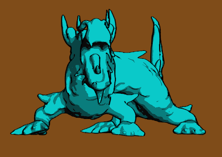
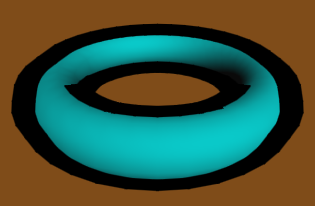
Here’s the final result:
Further Reading
These are some of the resources that gave me ideas for this blog post:
- There’s a nice article at Gamasutra about silhouette rendering with DirectX 10, written by an old colleague of mine, Josh Doss.
- Achieving AA by drawing lines on top of the model is called edge overdraw, which was written about in this 2001 paper by Hughes Hoppe and others.
- My silhouette lines are centered at the boundary, rather than extending only in the outwards direction. To achieve this, I use the “spine test”, which was introduced in a nice paper entitled Two Fast Methods for High-Quality Line Visibility, by Forrester Cole and Adam Finkelstein.
- To learn how to generate texture coordinates for fins (e.g., sketchy lines), and a different way of dealing with the gap between fins, check out a paper entitled Single Pass GPU Stylized Edges, by Hermosilla and Vázquez.
Downloads
The demo code uses a subset of the Pez ecosystem, which is included in the zip below.
I consider this code to be on the public domain.