Volumetric Splatting
Instanced rendering turns out to be useful for volumetric graphics. I first came across the concept in this excellent chapter in GPU Gems 3, which briefly mentions that instancing can voxelize a model in only 1 draw call using nothing but a quad. After reading this, I had the idea of using instancing to efficiently render volumetric splats. Splatting is useful for creating distance fields and Voronoi maps. It can also be used to extrude a streamline into a space-filling velocity field.
In this article, I show how volumetric splatting can be implemented efficiently with instancing. I show how to leverage splatting to extrude a circular streamline into a toroidal field of velocity vectors. This technique would allow an artist to design a large velocity field (e.g., for a particle system), simply by specifying a small animation path through space. My article also covers some basics of modern-day volume rendering on the GPU.
Volume Raycasting
Before I show you my raycasting shader, let me show you a neat trick to easily obtain the start and stop points for the rays. It works by drawing a cube into a pair of floating-point RGB surfaces, using a fragment shader that writes out object-space coordinates. Frontfaces go into one color attachment, backfaces in the other. This results in a tidy set of start/stop positions. Here are the shaders:
-- Vertex

in vec4 Position;
out vec3 vPosition;
uniform mat4 ModelviewProjection;

void main()
{
    gl_Position = ModelviewProjection * Position;
    vPosition = Position.xyz;
}

-- Fragment

in vec3 vPosition;
out vec3 FragData[2];

void main()
{
    if (gl_FrontFacing) {
        FragData[0] = 0.5 * (vPosition + 1.0);
        FragData[1] = vec3(0);
    } else {
        FragData[0] = vec3(0);
        FragData[1] = 0.5 * (vPosition + 1.0);
    }
}
Update: I recently realized that the pair of endpoint surfaces can be avoided by performing a quick ray-cube intersection in the fragment shader. I wrote a blog entry about it here.
You’ll want to first clear the surfaces to black, and enable simple additive blending for this to work correctly. Note that we’re using multiple render targets (MRT) to generate both surfaces in a single pass. To pull this off, you’ll need to bind a FBO that has two color attachments, then issue a glDrawBuffers command before rendering, like this:
GLenum renderTargets[2] = {GL_COLOR_ATTACHMENT0, GL_COLOR_ATTACHMENT1};
glDrawBuffers(2, &renderTargets[0]);
// Render cube...
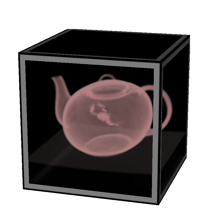
The next step is the actual raycasting, which is done by drawing a fullscreen quad with a longish fragment shader. We need to set up three texture samplers: two for the start/stop surfaces and one for the 3D volume texture itself. The following fragment shader performs raycasts against a single-channel 3D texture, which I used to generate the teapot image to the right. I obtained the scorpion-in-teapot volume data from this site at the University of Tübingen.
uniform sampler2D RayStart;
uniform sampler2D RayStop;
uniform sampler3D Volume;

out vec4 FragColor;
in vec3 vPosition;

uniform float StepLength = 0.01;

void main()
{
    vec2 coord = 0.5 * (vPosition.xy + 1.0);
    vec3 rayStart = texture(RayStart, coord).xyz;
    vec3 rayStop = texture(RayStop, coord).xyz;

    if (rayStart == rayStop) {
        discard;
        return;
    }

    vec3 ray = rayStop - rayStart;
    float rayLength = length(ray);
    vec3 stepVector = StepLength * ray/rayLength;

    vec3 pos = rayStart;
    vec4 dst = vec4(0);
    while (dst.a < 1 && rayLength > 0) {
        float density = texture(Volume, pos).x;
        vec4 src = vec4(density);
        src.rgb *= src.a;
        dst = (1.0 - dst.a) * src + dst;
        pos += stepVector;
        rayLength -= StepLength;
    }

    FragColor = dst;
}
Note the front-to-back blending equation inside the while loop; Benjamin Supnik has a good article about front-to-back blending on his blog. One advantage of front-to-back raycasting: it allows you to break out of the loop on fully-opaque voxels.
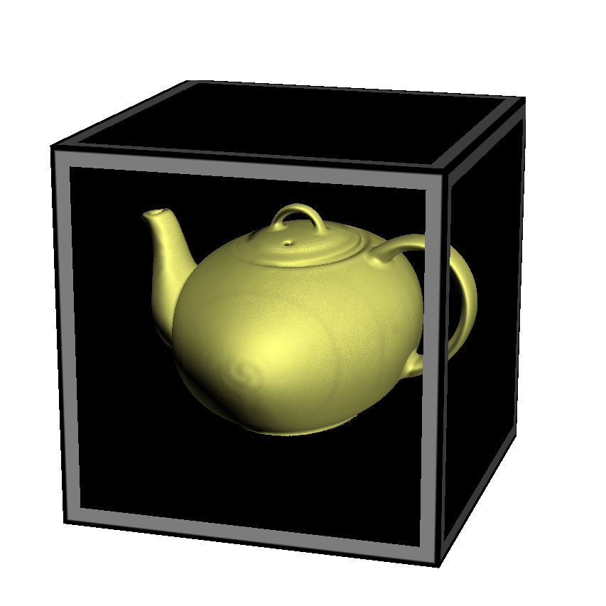
Volumetric Lighting
You’ll often want to create a more traditional lighting effect in your raycaster. For this, you’ll need to obtain surface normals somehow. Since we’re dealing with volume data, this might seem non-trivial, but it’s actually pretty simple.
Really there are two problems to solve: (1) detecting voxels that intersect surfaces in the volume data, and (2) computing the normal vectors at those positions. Turns out both of these problems can be addressed with an essential concept from vector calculus: the gradient vector points in the direction of greatest change, and its magnitude represents the amount of change. If we can compute the gradient at a particular location, we can check its magnitude to see if we’re crossing a surface. And, conveniently enough, the direction of the gradient is exactly what we want to use for our lighting normal!
The gradient vector is made up of the partial derivatives along the three axes; it can be approximated like this:
vec3 ComputeGradient(vec3 P)
{
    float L = StepLength;
    float E = texture(VolumeSampler, P + vec3(L,0,0));
    float N = texture(VolumeSampler, P + vec3(0,L,0));
    float U = texture(VolumeSampler, P + vec3(0,0,L));
    return vec3(E - V, N - V, U - V);
}
For the teapot data, we’ll compute the gradient for lighting normals only when the current voxel’s value is above a certain threshold. This lets us avoid making too many texture lookups. The shader looks like this:
out vec4 FragColor;
in vec3 vPosition;

uniform sampler2D RayStart;
uniform sampler2D RayStop;
uniform sampler3D Volume;

uniform float StepLength = 0.01;
uniform float Threshold = 0.45;

uniform vec3 LightPosition;
uniform vec3 DiffuseMaterial;
uniform mat4 Modelview;
uniform mat3 NormalMatrix;

float lookup(vec3 coord)
{
    return texture(Volume, coord).x;
}

void main()
{
    vec2 coord = 0.5 * (vPosition.xy + 1.0);
    vec3 rayStart = texture(RayStart, coord).xyz;
    vec3 rayStop = texture(RayStop, coord).xyz;

    if (rayStart == rayStop) {
        discard;
        return;
    }

    vec3 ray = rayStop - rayStart;
    float rayLength = length(ray);
    vec3 stepVector = StepLength * ray / rayLength;

    vec3 pos = rayStart;
    vec4 dst = vec4(0);
    while (dst.a < 1 && rayLength > 0) {

        float V = lookup(pos);
        if (V > Threshold) {

            float L = StepLength;
            float E = lookup(pos + vec3(L,0,0));
            float N = lookup(pos + vec3(0,L,0));
            float U = lookup(pos + vec3(0,0,L));
            vec3 normal = normalize(NormalMatrix * vec3(E - V, N - V, U - V));
            vec3 light = LightPosition;

            float df = abs(dot(normal, light));
            vec3 color = df * DiffuseMaterial;

            vec4 src = vec4(color, 1.0);
            dst = (1.0 - dst.a) * src + dst;
            break;
        }

        pos += stepVector;
        rayLength -= StepLength;
    }

    FragColor = dst;
}
Reducing Slice Artifacts
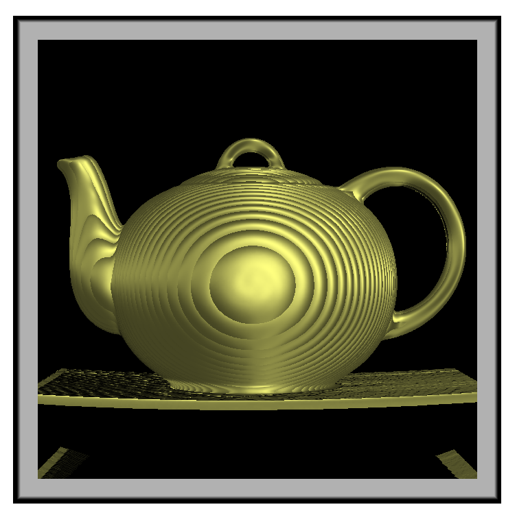
When writing your first volume renderer, you’ll undoubtedly come across the scourge of “wood grain” artifacts; your data will look like it’s made up of a stack of slices (which it is!). Obviously, reducing the raycast step size can help with this, but doing so can be detrimental to performance.
There are a couple popular tricks that can help: (1) re-checking the “solidity” of the voxel by jumping around at half-step intervals, and (2) jittering the ray’s starting position along the view direction. I added both of these tricks into our fragment shader; they’re highlighted in gray here:
// ...same as before...

uniform sampler2D Noise;

void main()
{
    // ...same as before...

    rayStart += stepVector * texture(Noise, gl_FragCoord.xy / 256).r;

    vec3 pos = rayStart;
    vec4 dst = vec4(0);
    while (dst.a < 1 && rayLength > 0) {

        float V = lookup(pos);
        if (V > Threshold) {

            vec3 s = -stepVector * 0.5;
            pos += s; V = lookup(pos);
            if (V > Threshold) s *= 0.5; else s *= -0.5;
            pos += s; V = lookup(pos);

            if (V > Threshold) {
                // ...same as before...
            }
        }

        pos += stepVector;
        rayLength -= StepLength;
    }

    FragColor = dst;
}
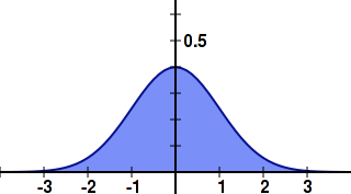
3D Gaussian Splat
Now that we’ve covered the basics of volume rendering, let’s come back to the main subject of this article, which deals with the generation of volumetric data using Gaussian splats.
One approach would be evaluating the 3D Gaussian function on the CPU during application initialization, and creating a 3D texture from that. However, I find it to be faster to simply compute the Gaussian in real-time, directly in the fragment shader.
Recall that we’re going to use instancing to render all the slices of the splat with only 1 draw call. One awkward aspect of GLSL is that the gl_InstanceID input variable is only accessible from the vertex shader, while the gl_Layer output variable is only accessible from the geometry shader. It’s not difficult to deal with this though! Without further ado, here’s the trinity of shaders for 3D Gaussian splatting:
-- Vertex Shader

in vec4 Position;
out vec2 vPosition;
out int vInstance;
uniform vec4 Center;

void main()
{
    gl_Position = Position + Center;
    vPosition = Position.xy;
    vInstance = gl_InstanceID;
}

-- Geometry Shader

layout(triangles) in;
layout(triangle_strip, max_vertices = 3) out;

in int vInstance[3];
in vec2 vPosition[3];
out vec3 gPosition;

uniform float InverseSize;

void main()
{
    gPosition.z = 1.0 - 2.0 * vInstance[0] * InverseSize;
    gl_Layer = vInstance[0];

    gPosition.xy = vPosition[0];
    gl_Position = gl_in[0].gl_Position;
    EmitVertex();

    gPosition.xy = vPosition[1];
    gl_Position = gl_in[1].gl_Position;
    EmitVertex();

    gPosition.xy = vPosition[2];
    gl_Position = gl_in[2].gl_Position;
    EmitVertex();

    EndPrimitive();
}

-- Fragment Shader

in vec3 gPosition;
out vec3 FragColor;

uniform vec3  Color;
uniform float InverseVariance;
uniform float NormalizationConstant;

void main()
{
    float r2 = dot(gPosition, gPosition);
    FragColor = Color * NormalizationConstant * exp(r2 * InverseVariance);
}
Setting up a 3D texture as a render target might be new to you; here’s one way you could set up the FBO: (note that I’m calling glFramebufferTexture rather than glFramebufferTexture{2,3}D)
struct Volume {
    GLuint FboHandle;
    GLuint TextureHandle;
};

Volume CreateVolume(GLsizei width, GLsizei height, GLsizei depth)
{
    Volume volume;
    glGenFramebuffers(1, &volume.FboHandle);
    glBindFramebuffer(GL_FRAMEBUFFER, volume.FboHandle);

    GLuint textureHandle;
    glGenTextures(1, &textureHandle);
    glBindTexture(GL_TEXTURE_3D, textureHandle);
    glTexParameteri(GL_TEXTURE_3D, GL_TEXTURE_WRAP_S, GL_CLAMP_TO_EDGE);
    glTexParameteri(GL_TEXTURE_3D, GL_TEXTURE_WRAP_T, GL_CLAMP_TO_EDGE);
    glTexParameteri(GL_TEXTURE_3D, GL_TEXTURE_WRAP_R, GL_CLAMP_TO_EDGE);
    glTexParameteri(GL_TEXTURE_3D, GL_TEXTURE_MIN_FILTER, GL_LINEAR);
    glTexParameteri(GL_TEXTURE_3D, GL_TEXTURE_MAG_FILTER, GL_LINEAR);
    glTexImage3D(GL_TEXTURE_3D, 0, GL_RGB16F, width, height, depth, 0,
                 GL_RGB, GL_HALF_FLOAT, 0);
    volume.TextureHandle = textureHandle;

    GLint miplevel = 0;
    GLuint colorbuffer;
    glGenRenderbuffers(1, &colorbuffer);
    glBindRenderbuffer(GL_RENDERBUFFER, colorbuffer);
    glFramebufferTexture(GL_FRAMEBUFFER, GL_COLOR_ATTACHMENT0, textureHandle, miplevel);

    return volume;
}
Note that we created a half-float RGB texture for volume rendering — this might seem like egregious usage of memory, but keep in mind that our end goal is to create a field of velocity vectors.
Flowline Extrusion
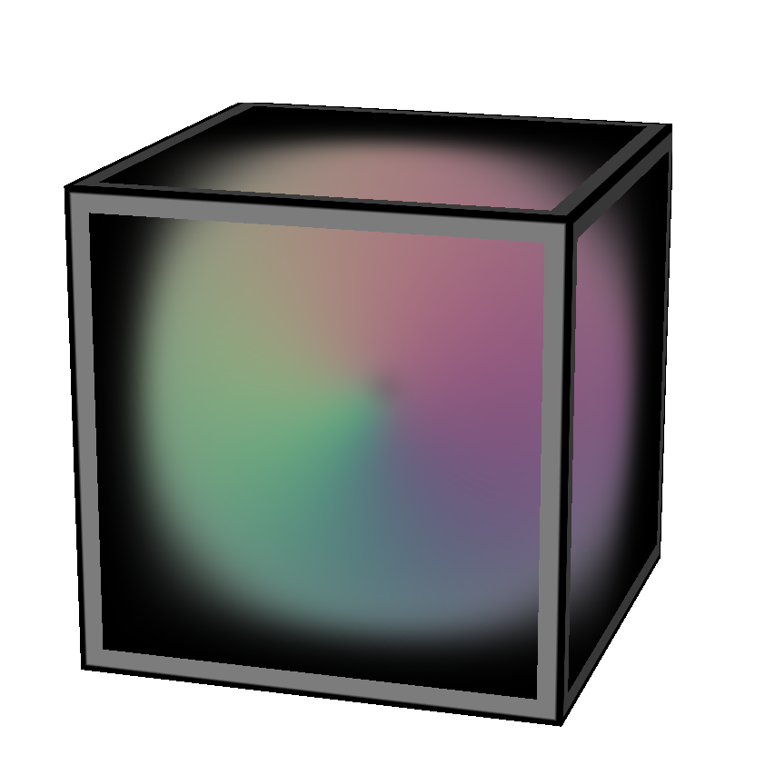
Now that we have the splat shaders ready, we can write the C++ code that extrudes a vector of positions into a velocity field. It works by looping over the positions in the path, computing the velocity at that point, and splatting the velocity. The call to glDrawArraysInstanced is simply rendering a quad with the instance count set to the depth of the splat.
typedef std::vector<VectorMath::Point3> PointList;

glEnable(GL_BLEND);
glBlendFunc(GL_ONE, GL_ONE);

PointList::const_iterator i = positions.begin();
for (; i != positions.end(); ++i) {

    PointList::const_iterator next = i;
    if (++next == positions.end())
        next = positions.begin();
    VectorMath::Vector3 velocity = (*next - *i);

    GLint center = glGetUniformLocation(program, "Center");
    glUniform4f(center, i->getX(), i->getY(), i->getZ(), 0);

    GLint color = glGetUniformLocation(program, "Color");
    glUniform3fv(color, 1, (float*) &velocity);

    glDrawArraysInstanced(GL_TRIANGLE_STRIP, 0, 4, Size);
}
Blending is essential for this to work correctly. If you want to create a true distance field, you’d want to use GL_MAX blending rather than the default blending equation (which is GL_FUNC_ADD), and you’d want your fragment shader to use evaluate a linear falloff rather than the Gaussian function.
Velocity Visualization
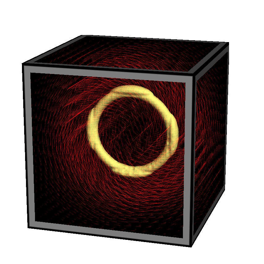
One popular way to visualize a grid of velocities is via short lines with alpha gradients, as in the image to the right (click to enlarge). This technique is easy to implement with modern OpenGL. Simply populate a VBO with a single point per grid cell, then use the geometry shader to extrude each point into a short line segment whose length and direction reflects the velocity vector in that cell. It’s rather beautiful actually! Here’s the shader triplet:
-- Vertex Shader

in vec4 Position;
out vec4 vPosition;
uniform mat4 ModelviewProjection;

void main()
{
    gl_Position = ModelviewProjection * Position;
    vPosition = Position;
}

-- Geometry Shader

layout(points) in;
layout(line_strip, max_vertices = 2) out;
out float gAlpha;
uniform mat4 ModelviewProjection;
in vec4 vPosition[1];
uniform sampler3D Volume;

void main()
{
    vec3 coord = 0.5 * (vPosition[0].xyz + 1.0);
    vec4 V = vec4(texture(Volume, coord).xyz, 0.0);

    gAlpha = 0;
    gl_Position = gl_in[0].gl_Position;
    EmitVertex();

    gAlpha = 1;
    gl_Position = ModelviewProjection * (vPosition[0] + V);
    EmitVertex();

    EndPrimitive();
}

-- Fragment Shader

out vec4 FragColor;
in float gAlpha;
uniform float Brightness = 0.5;

void main()
{
    FragColor = Brightness * vec4(gAlpha, 0, 0, 1);
}
Downloads
The demo code uses a subset of the Pez ecosystem, which is included in the zip below. It uses CMake for the build system.
I consider this code to be on the public domain. Enjoy!